Stock high beams --> DRL's?
 07-15-2010, 03:36 PM
#1
Stock high beams --> DRL's?
I'm interested in turning my stock high beams on my 99 TL into DRL's but I'm not sure if this is possible. The only kits I can find anywhere are for LED's and for cars that already have stock DRL's. Has anyone done this mod or know of a good kit/module?
 07-15-2010, 09:35 PM
#2
Senior Moderator
 07-16-2010, 04:43 PM
#3
I must be searching for the wrong keywords, but I can't find anything. it's just a 9005 DRL kit, right? everything I find is either for LED's or includes bulbs
is this appicable? http://www.hidkits.net/p5-HID-Relay-Wiring-Harness.html
is this appicable? http://www.hidkits.net/p5-HID-Relay-Wiring-Harness.html
Last edited by Tay119; 07-16-2010 at 04:50 PM.
07-16-2010, 05:12 PM
#5
i dunno if this will work for the TL but try it.. it shouldn't cost to much
Video of this mod: http://www.youtube.com/watch?v=SVF5eAG5GTg
Video of mode 2, DRL remains on with low beams on: http://www.youtube.com/watch?v=qyddEUHc8C8
First and foremost, credit where credit is due. I would like give thanks and credit to Andrew of Alavigne.net for creating the original DRL modification on his USDM S2000. After reviewing Andrew's original framework to implement working DRLs on his USDM S2000, I was able to adapt his instructions for use on the USDM RSX. His original instructions can be viewed at http://alavigne.net/Motorsports/Feat.../DRL/index.jsp. Without the instructions written by Andrew (with the help of his friend Markus), this DIY would never reach fruition.
If you understand how 5-lead automotive relay works and have knowledge on basic wiring techniques (splicing, cutting, crimping), you can skip the instructions and look at the connection diagram at the end of this DIY.
And finally, for all your wiring needs (anything you can possibly think of, terminals, connects, fuse, wires, relays, terminal joints, connectors, resistors, diodes, etc. etc.), go to www.mouser.com. They're top notch.
Edit: This mod is not for folks who swapped in HID for their high beams. HID ballasts require 100% power for normal operation
I. Preparation
The instructions prepared are written with utmost detail with OEM quality in mind and reversible wire work implemented. You can save time if you sacrifice some or most of the steps and use the diagram to directly rig the connections.
1a. Required parts
1 Hamsar 45060 DRL - order through www.terminalsupplyco.com, 800-989-9632. Part #: HS-45060, $60.60 + tax and shipping. Ask for Sally @ x1140. Two weeks backorder status. You need the 45060 unit as it is designed for use on cars with a 2 headlight system. This part is the crown jewel of this project.

1 9005 male connector w/pigtail (or H4/H7 male connector for '02-'04 model; see II).

1 40/30A automotive relay - Radio Shack or any automotive parts store, i.e. Pep Boys, AutoZone, etc.

1 Reel of 14-16 AWG wire, any color. You can use multi-color for color coordination, but it gets pricey. As you'll see, we'll label the wires to identify each connection. 20 feet of wire should suffice.

1 14-16 AWG inline fuse holder w/15A blade fuse, any automotive parts store, i.e. Pepboys, AutoZone, etc. Ordered mines through Mouser.com, part #: 576-FHM001 (shown with mini fuse holder, you can use standard size fuse holder - I just happen to have many mini fuses lying around and one of them is 15A)

14-16 AWG fork terminal connects - any automotive parts store, I've ordered bulk qty for future projects through Mouser.com, part #: 644-PV14-8FX-M. For a more secure install, you may want to use o-ring terminal connects instead. I used what I had available.

14-16 AWG female quick disconnects - any automotive parts store, I've ordered bulk qty for future projects through Mouser.com, part #: 538-19003-0052

14-16 AWG male quick disconnects (shown non-insulated 10 AWG for the purpose of illustration; I highly recommend insulated quick connects) - any automotive parts store, I've ordered bulk qty for future projects through Mouser.com, part #: 538-19001-0008

14-16 AWG T-taps - any automotive parts store:

Total cost of project: between $75-$160, depending on how you tackle the project.
Hours required: No more than 45 minutes to an hour.
1a2. Required tools & miscellaneous parts
efore wiring up the relays, it is a good practice to find a mounting spot for them. Not only will you save time mounting the relays later, it also give you a sense of distance from the work area, i.e. you'll have good judgement on how long to make patch wires, extensions, etc.
For this mod, the I used location is this spot where the stock airbox use to bolt onto:

Take a strip of industrial tape and tape the two relays together, ensuring a tight attachment. I applied a few strips of 3M industrial automotive tape between the automotive relay and Hamsar DRL relay to ensure a tight fitting adhesion. Mount the automotive relay with the Hamsar relay attached piggyback style onto the mounting location with a 10mm bolt. Make sure the location is secure and that you can close your hood without hitting the relays.
1c. Creating high beam replica female connectorsThere are several ways of performing this mod. Above all, keep in mind that this mod was performed on a 2005 model USDM RSX. Obviously, the high beam connectors will differ from a 2002-2004 model (as all the folks who did an 05-06 conversion will know), but the high beam wire color identification (i.e. RED/YEL, RED, RED/BLU, etc.) should be the same. Use common sense when you work on this mod and adapt accordingly to your specific application.
Your available options:
The ghetto-rigged freebie method
You can ghetto-rig the set up by cutting and splicing your stock hight beam connectors and wire harness. This route is the cheapest but causes permanent damage to your OEM wire harness. Basically, instead of using replacement high beam connectors as described in option 2 and 3, you use your OEM high beam connectors and perform the required wire splicing and cutting as illustrated in the subsequent instructions and diagrams. If you want a seamless OEM-reversible installation, then you might want to follow option 2 or 3 instead. If you want instant gratification and don't want to spend or wait for parts, this is the way to go.
The cost effective method, yet OEM-reversible
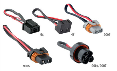
You can go to a junkyard and cut or purchase two used female 2-pin high beam connectors with trailing pigtails from a junked RSX. If you go with this route, be sure to cut out the right connectors for your RSX year model (i.e., H4 3-pin connectors for 2002-2004 models, 2-pin 9005 connectors for 2005-2006 models). Doesn't exactly have to be from an RSX as long as the parts are either compatible female H4/H7 or 9005 connectors with pigtails. Be sure to have two wires coming out of each connectors. This is the most cost efficient route.
You can also buy the 9005 harness or the H4/H7 harness from local auto parts store or eBay (search for "9005 wiring harness") for a fraction of a cost. I believe H4 connectors are compatible with either H4 or H7. 2002-2004 RSX owners, again, double check for accuracy. Expect to shell out between $5-$15 for these pre-made harness.
The OEM-reversible but costliest method (i.e. making your own OEM replica connectors)
Or you can create a new set of high beam connectors by ordering two brand new high beam connectors from Acura and corresponding pigtails. This is what I've done because I have a healthy supply of connectors and pigtails from a previous project and the subsequent DIY instructions will illustrate my procedure. Ultimately this is also the costliest option (costing up to $61.00 for genuine OEM parts alone). By following this route or Option 2, you leave your OEM high beam connectors and wire harness intact. To create a new set of OEM high beam connectors from scratch, the following parts are required:
2002-2004 models
04321-S2G-305 - CONNECTOR (3P 321F)
04320-SP0-K10 - SUB-CORD (1.25) (10 PIECES) (RED)
2002-2004 RSX owners, double check and ensure the parts and part #s are accurate before you order the parts. I make no warranty that the part #s are accurate.
2005-2006 models
04321-SH3-305 - CONNECTOR (2P 110F) (5 PIECES)

04320-SP0-N00 - PIGTAIL (1.25) (10 PIECES) (RED)

Before you insert the pigtails into the connector terminals, make sure the orientation and direction of the terminal joints are correct.
Take the pigtails and secure the terminal joint into the terminals of each connector to create a brand new replacement high beam connector like this:

Top off the connector with a corresponding terminal cap:
Create a second replica high beam connector for a total of one pair:

Again, to save on cost, you can purchase pre-assembled 9005 (or H4/H7 for '02-'04 owners) female connectors w/pigtails!
Next pair up the newly created replica high beam connectors with the OEM connectors for a side by side comparison. Take a piece of masking tape and write down the wire color identification on the OEM connectors and then apply the tape to the corresponding wires of the replica connectors. We'll be using the replica connectors as if they are the OEM connectors, leaving the actual OEM connectors unscathed. To access the right OEM connector, you will have to remove the power steering fluid reservoir by unbolting a 10mm bolt:

Here are the left and right connectors with proper labeling. We're simply making replica OEM high beam connectors with correct wire polarity.
Right headlight/passenger side replica high beam connector:

Left headlight/driver side replica high beam connector

Once the pigtails are secured snuggly into the connectors and you've identified the wire colors of your replica connectors, we're good to go. Take a 14-16 AWG fork crimp-on terminal and crimp it onto the pigtails identified as RED/BLU on both replica connectors.
Take a 14-16 AWG female quick disconnect and crimp it on the remaining pigtails identified as RED and RED/YEL:

Take a 3 feet 14 AWG patch wire and then strip 1/4" from both end, using a wire stripped. Then crimp a 14-16 AWG male quick disconnect onto each end:

Connect one end of the 3 feet patch wire to the wire identified as "RED" on the replica left high beam connector and connect the other end to the wire identified as "RED/YEL" on the replica right high beam replica connector. By doing this, you've effectively connected the RED/YEL wire of the replica left high beam connector with the RED wire of the replica right high beam connector, forming a single bridged connection.
Attach a 14-16 AWG T-Tap somewhere along the bridged patch wire, preferably close to the left headlight. Then finally, make a 2 feet patch wire and attach a female quick disconnect on one end and a male quick disconnect on the other end. Connect the male quick disconnect to the T-Tap crimped onto the bridged patch wire and label this new patch wire with a masking tape as "30 AR":

Unplug both OEM high beam connectors from the high beam bulbs, then plug in the replica high beam connectors onto the high beam bulbs. Ground the RED/BLU wire from each of the high beam replica connectors by securing them onto a bolt along the chassis:

We're done with the high beam connectors for now.
Video of mode 2, DRL remains on with low beams on: http://www.youtube.com/watch?v=qyddEUHc8C8
First and foremost, credit where credit is due. I would like give thanks and credit to Andrew of Alavigne.net for creating the original DRL modification on his USDM S2000. After reviewing Andrew's original framework to implement working DRLs on his USDM S2000, I was able to adapt his instructions for use on the USDM RSX. His original instructions can be viewed at http://alavigne.net/Motorsports/Feat.../DRL/index.jsp. Without the instructions written by Andrew (with the help of his friend Markus), this DIY would never reach fruition.
If you understand how 5-lead automotive relay works and have knowledge on basic wiring techniques (splicing, cutting, crimping), you can skip the instructions and look at the connection diagram at the end of this DIY.
And finally, for all your wiring needs (anything you can possibly think of, terminals, connects, fuse, wires, relays, terminal joints, connectors, resistors, diodes, etc. etc.), go to www.mouser.com. They're top notch.
Edit: This mod is not for folks who swapped in HID for their high beams. HID ballasts require 100% power for normal operation
I. Preparation
The instructions prepared are written with utmost detail with OEM quality in mind and reversible wire work implemented. You can save time if you sacrifice some or most of the steps and use the diagram to directly rig the connections.
1a. Required parts
1 Hamsar 45060 DRL - order through www.terminalsupplyco.com, 800-989-9632. Part #: HS-45060, $60.60 + tax and shipping. Ask for Sally @ x1140. Two weeks backorder status. You need the 45060 unit as it is designed for use on cars with a 2 headlight system. This part is the crown jewel of this project.
1 9005 male connector w/pigtail (or H4/H7 male connector for '02-'04 model; see II).
1 40/30A automotive relay - Radio Shack or any automotive parts store, i.e. Pep Boys, AutoZone, etc.
1 Reel of 14-16 AWG wire, any color. You can use multi-color for color coordination, but it gets pricey. As you'll see, we'll label the wires to identify each connection. 20 feet of wire should suffice.
1 14-16 AWG inline fuse holder w/15A blade fuse, any automotive parts store, i.e. Pepboys, AutoZone, etc. Ordered mines through Mouser.com, part #: 576-FHM001 (shown with mini fuse holder, you can use standard size fuse holder - I just happen to have many mini fuses lying around and one of them is 15A)
14-16 AWG fork terminal connects - any automotive parts store, I've ordered bulk qty for future projects through Mouser.com, part #: 644-PV14-8FX-M. For a more secure install, you may want to use o-ring terminal connects instead. I used what I had available.
14-16 AWG female quick disconnects - any automotive parts store, I've ordered bulk qty for future projects through Mouser.com, part #: 538-19003-0052
14-16 AWG male quick disconnects (shown non-insulated 10 AWG for the purpose of illustration; I highly recommend insulated quick connects) - any automotive parts store, I've ordered bulk qty for future projects through Mouser.com, part #: 538-19001-0008
14-16 AWG T-taps - any automotive parts store:
Total cost of project: between $75-$160, depending on how you tackle the project.
Hours required: No more than 45 minutes to an hour.
1a2. Required tools & miscellaneous parts
- 10mm socket & ratchet wrench (or 10mm wrench)
- wire cutter and stripper
- terminal crimping tool (most wire stripper has one built-in)
- heat shrinking tube (optional)
- pen & masking tape
- industrial vinyl tape
- heat shrinking tube (optional)
efore wiring up the relays, it is a good practice to find a mounting spot for them. Not only will you save time mounting the relays later, it also give you a sense of distance from the work area, i.e. you'll have good judgement on how long to make patch wires, extensions, etc.
For this mod, the I used location is this spot where the stock airbox use to bolt onto:
Take a strip of industrial tape and tape the two relays together, ensuring a tight attachment. I applied a few strips of 3M industrial automotive tape between the automotive relay and Hamsar DRL relay to ensure a tight fitting adhesion. Mount the automotive relay with the Hamsar relay attached piggyback style onto the mounting location with a 10mm bolt. Make sure the location is secure and that you can close your hood without hitting the relays.
1c. Creating high beam replica female connectorsThere are several ways of performing this mod. Above all, keep in mind that this mod was performed on a 2005 model USDM RSX. Obviously, the high beam connectors will differ from a 2002-2004 model (as all the folks who did an 05-06 conversion will know), but the high beam wire color identification (i.e. RED/YEL, RED, RED/BLU, etc.) should be the same. Use common sense when you work on this mod and adapt accordingly to your specific application.
Your available options:
The ghetto-rigged freebie method
You can ghetto-rig the set up by cutting and splicing your stock hight beam connectors and wire harness. This route is the cheapest but causes permanent damage to your OEM wire harness. Basically, instead of using replacement high beam connectors as described in option 2 and 3, you use your OEM high beam connectors and perform the required wire splicing and cutting as illustrated in the subsequent instructions and diagrams. If you want a seamless OEM-reversible installation, then you might want to follow option 2 or 3 instead. If you want instant gratification and don't want to spend or wait for parts, this is the way to go.
The cost effective method, yet OEM-reversible
You can go to a junkyard and cut or purchase two used female 2-pin high beam connectors with trailing pigtails from a junked RSX. If you go with this route, be sure to cut out the right connectors for your RSX year model (i.e., H4 3-pin connectors for 2002-2004 models, 2-pin 9005 connectors for 2005-2006 models). Doesn't exactly have to be from an RSX as long as the parts are either compatible female H4/H7 or 9005 connectors with pigtails. Be sure to have two wires coming out of each connectors. This is the most cost efficient route.
You can also buy the 9005 harness or the H4/H7 harness from local auto parts store or eBay (search for "9005 wiring harness") for a fraction of a cost. I believe H4 connectors are compatible with either H4 or H7. 2002-2004 RSX owners, again, double check for accuracy. Expect to shell out between $5-$15 for these pre-made harness.
The OEM-reversible but costliest method (i.e. making your own OEM replica connectors)
Or you can create a new set of high beam connectors by ordering two brand new high beam connectors from Acura and corresponding pigtails. This is what I've done because I have a healthy supply of connectors and pigtails from a previous project and the subsequent DIY instructions will illustrate my procedure. Ultimately this is also the costliest option (costing up to $61.00 for genuine OEM parts alone). By following this route or Option 2, you leave your OEM high beam connectors and wire harness intact. To create a new set of OEM high beam connectors from scratch, the following parts are required:
2002-2004 models
04321-S2G-305 - CONNECTOR (3P 321F)
04320-SP0-K10 - SUB-CORD (1.25) (10 PIECES) (RED)
2002-2004 RSX owners, double check and ensure the parts and part #s are accurate before you order the parts. I make no warranty that the part #s are accurate.
2005-2006 models
04321-SH3-305 - CONNECTOR (2P 110F) (5 PIECES)
04320-SP0-N00 - PIGTAIL (1.25) (10 PIECES) (RED)
Before you insert the pigtails into the connector terminals, make sure the orientation and direction of the terminal joints are correct.
Take the pigtails and secure the terminal joint into the terminals of each connector to create a brand new replacement high beam connector like this:
Top off the connector with a corresponding terminal cap:
Create a second replica high beam connector for a total of one pair:
Again, to save on cost, you can purchase pre-assembled 9005 (or H4/H7 for '02-'04 owners) female connectors w/pigtails!
Next pair up the newly created replica high beam connectors with the OEM connectors for a side by side comparison. Take a piece of masking tape and write down the wire color identification on the OEM connectors and then apply the tape to the corresponding wires of the replica connectors. We'll be using the replica connectors as if they are the OEM connectors, leaving the actual OEM connectors unscathed. To access the right OEM connector, you will have to remove the power steering fluid reservoir by unbolting a 10mm bolt:
Here are the left and right connectors with proper labeling. We're simply making replica OEM high beam connectors with correct wire polarity.
Right headlight/passenger side replica high beam connector:
Left headlight/driver side replica high beam connector
Once the pigtails are secured snuggly into the connectors and you've identified the wire colors of your replica connectors, we're good to go. Take a 14-16 AWG fork crimp-on terminal and crimp it onto the pigtails identified as RED/BLU on both replica connectors.
Take a 14-16 AWG female quick disconnect and crimp it on the remaining pigtails identified as RED and RED/YEL:
Take a 3 feet 14 AWG patch wire and then strip 1/4" from both end, using a wire stripped. Then crimp a 14-16 AWG male quick disconnect onto each end:
Connect one end of the 3 feet patch wire to the wire identified as "RED" on the replica left high beam connector and connect the other end to the wire identified as "RED/YEL" on the replica right high beam replica connector. By doing this, you've effectively connected the RED/YEL wire of the replica left high beam connector with the RED wire of the replica right high beam connector, forming a single bridged connection.
Attach a 14-16 AWG T-Tap somewhere along the bridged patch wire, preferably close to the left headlight. Then finally, make a 2 feet patch wire and attach a female quick disconnect on one end and a male quick disconnect on the other end. Connect the male quick disconnect to the T-Tap crimped onto the bridged patch wire and label this new patch wire with a masking tape as "30 AR":
Unplug both OEM high beam connectors from the high beam bulbs, then plug in the replica high beam connectors onto the high beam bulbs. Ground the RED/BLU wire from each of the high beam replica connectors by securing them onto a bolt along the chassis:
We're done with the high beam connectors for now.
07-16-2010, 05:12 PM
#6
Part2.
1d. Tap into the ign wire
take the 3 feet grn wire from the hamsar drl relay and run it from the engine bay and into the cabin. This is the hardest part of the install. Start by removing the two tapping screw from the left inner fender liner:

run the grn wire across the engine bay and through the left fender:

(image shows grn wire with male quick disconnect crimped on, do not do this as you'll see why)
pull the inner fender liner and look for a grommet where your hood release cable passes through. Pull this grommet out of its socket:

then insert the grn wire from the hamsar drl relay unit through the grommet and insert as much of the grn wire as you can:

re-install the grommet back into its socket. You may need to use a flat head screwdriver for assistant:

inside the cabin, remove the kick panel covering the hood release latch and pull the green wire you've just inserted:

most likely, the grn wire will not reach the ignition switch. I attached a 1 foot patch wire onto the end of the grn wire, then crimped a male quick disconnect onto the attached patch wire.
Remove the ignition cover and find the blk/yel wire. This is the ignition wire. It becomes active when the ignition is turn to the ii position. Once the connections are completed, simply putting your key to the ii position will activate the drls.
You want to take the male ended part of the patch wire and tap it into the blk/yel ignition wire:

a.) you can put attach a 10-12 awg female t-tap onto the blk/yel wire and complete the connection with the patch wire this way (safest).
B.) you can tap into another wire source that also utilizes the blk/yel wire, i.e. An alarm system (illustrated).

whichever method you used to tap the patch wire into the ignition wire, make sure no metal terminals are exposed as you may inadvertently cause a short and blow a fuse. Tape up any exposed terminals (especially if the male disconnect is not insulated) and set the patch wire aside.
ii. High beam dummy male connector
to activate the high beams under normal high beam mode or flash-to-pass mode, we need to send an electrical current to the relays that will cause it to draw full power from the battery when the combination switch is set in either high beam or flash-to-pass.
Again, you can ghetto-rig this setup by cutting or splicing a patch wire to the red/blu wire that's attached to the left oem high beam connector.
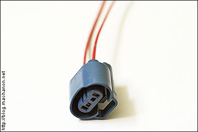
What i did instead, for a clean install, was ordered a set of pre-assembled 9005 male connectors from ebay. 2002-2004 owners, you'll need the h7 connector. You only need to make use of one dummy high beam male connector.
H7 male connectors example [for 2002-2004 rsx models]

then i plugged the left oem high beam connector into the dummy socket to check the position and identify the polarity of the wires.
I then attached a 1.5 feet patch wire with a 14-16 awg female quick disconnect crimped to one end, onto the end of the pigtail that is aligned with the red/blu wire from the oem connector with a butt connector, labeling it as "high beam red/blu 85 ar".
I attached a 1.5 feet patch wire, crimped a 14-16 awg female quick disconnect on the end, to the remaining pigtail with another butt crimp connector and labeled that pigtail as "red/yel 86 ar 86 hs":

attach a t-tap to the wire you've just labeled "red/yel 86 ar 86 hs" close to the end of the wire, near the female quick disconnect.
For 2002-2004 models, you can take a non insulated male blade quick disconnect and crimp it onto a 14 awg patch wire and insert it into the terminal of the left oem high beam connector that corresponds to the red/blu wire, and repeat the process for the red/yel wire instead of making or buying premade dummy male connectors.
Once you've completed this step, let the patch wire hang on a visible part of the vehicle's chassis. We'll complete the connection in a few steps down.
We are done with this step.
iii. Making the connections
by now, you should have labeled four wires:
Before proceeding, strip 1/4" from the end of the org wire that is coming out of the hamsar drl relay plug and then attach a 14-16 awg male quick disconnect to the end of the org wire. Crimp a 14-16 awg female quick disconnect to the end of the wht wire. For the blk and red wires, leave them alone as they already have end terminals pre-crimped:

depending on where you mount the relay, you may want to shorten the hamsar drl relay wires for a clean connection. I shortened the wht and org wires to 6".
connecting:
connect the fork terminal connect end of the 15a inline fuse holder to the positive terminal of the battery. Then take the male quick disconnect end of the 15a inline fuse holder and connect it to one female end of the patch wire labeled 87 ar. Take the remaining end of the patch wire labeled 87 ar and connect it to pin 87 of the automotive relay.
Take the red wire from the hamsar drl relay. The red wire should contain an inline fuse holder with a 10a blade fuse in the holder and is connected to pin 87a of the hamsar drl relay. Take the ring terminal and connect it to the positive terminal of the battery.
The finalized interconnectivity of wires between the high beam connectors, automotive relay and hamsar drl relay should similar to this:


what this all means
when you turn your key to the ii position of the ignition, pin 85 of the hamsar drl relay is energized. This draws an electrical current from the battery through pin 87a and sends it to pin 30 of the hamsar drl relay (the circuit that sends out reduced currents), which then gets transferred at 60% intensity to pin 87a of the automotive relay. The 60% intensity current then energizes pin 30 of the automotive relay, which then powers the high beams at reduced 60% intensity.
Now if you operate the high beams or engage in flash-to-pass mode, pin 86 of the automotive relay becomes energized and the circuit between pin 30 and pin 87 of the automotive relay is bridged and the drl unit is grounded (powered off). Now instead of receiving 60% current through pin 87a of the automotive relay, the high beams are now powered at 100% intensity by the battery through the bridge formed by pin 30 and pin 87 of the automotive relay.
iv. Testing the connections
before we wrap everything up, let's make sure the connections are correct. Make sure all the ground terminal connects are properly grounded to a metallic surface on the vehicle chassis (3 wires). Make sure all power terminal are properly connected to the positive terminal of the battery (2 wires).
Ensure that the light combination switch works properly with the car off. Test the high beam, low beam and flash to pass switches to ensure proper operation. Once you've confirmed that the lights operate normally while the car is off, take your key and insert it into the ignition.

turn it to the ii position and step out of your car to look at your headlights. Wait 5 seconds, the drl should turn on - that is, your high beams should turn on, but at 60% of the intensity:


now if you've gone this far, turn on your low beams. Your drl should now be off:


turn on your high beams with your low beams on. Your high beam should operate at 100% intensity:


now turn off your high beams but allow your low beams to remain on. Hit flash-to-pass and your high beam should operate at 100% intensity. You may need an assistant to confirm this.
Videos of the setup can be seen here: http://www.youtube.com/watch?v=svf5eag5gtg
take the 3 feet grn wire from the hamsar drl relay and run it from the engine bay and into the cabin. This is the hardest part of the install. Start by removing the two tapping screw from the left inner fender liner:
run the grn wire across the engine bay and through the left fender:
(image shows grn wire with male quick disconnect crimped on, do not do this as you'll see why)
pull the inner fender liner and look for a grommet where your hood release cable passes through. Pull this grommet out of its socket:
then insert the grn wire from the hamsar drl relay unit through the grommet and insert as much of the grn wire as you can:
re-install the grommet back into its socket. You may need to use a flat head screwdriver for assistant:
inside the cabin, remove the kick panel covering the hood release latch and pull the green wire you've just inserted:
most likely, the grn wire will not reach the ignition switch. I attached a 1 foot patch wire onto the end of the grn wire, then crimped a male quick disconnect onto the attached patch wire.
Remove the ignition cover and find the blk/yel wire. This is the ignition wire. It becomes active when the ignition is turn to the ii position. Once the connections are completed, simply putting your key to the ii position will activate the drls.
You want to take the male ended part of the patch wire and tap it into the blk/yel ignition wire:
a.) you can put attach a 10-12 awg female t-tap onto the blk/yel wire and complete the connection with the patch wire this way (safest).
B.) you can tap into another wire source that also utilizes the blk/yel wire, i.e. An alarm system (illustrated).
whichever method you used to tap the patch wire into the ignition wire, make sure no metal terminals are exposed as you may inadvertently cause a short and blow a fuse. Tape up any exposed terminals (especially if the male disconnect is not insulated) and set the patch wire aside.
ii. High beam dummy male connector
to activate the high beams under normal high beam mode or flash-to-pass mode, we need to send an electrical current to the relays that will cause it to draw full power from the battery when the combination switch is set in either high beam or flash-to-pass.
Again, you can ghetto-rig this setup by cutting or splicing a patch wire to the red/blu wire that's attached to the left oem high beam connector.
What i did instead, for a clean install, was ordered a set of pre-assembled 9005 male connectors from ebay. 2002-2004 owners, you'll need the h7 connector. You only need to make use of one dummy high beam male connector.
H7 male connectors example [for 2002-2004 rsx models]
then i plugged the left oem high beam connector into the dummy socket to check the position and identify the polarity of the wires.
I then attached a 1.5 feet patch wire with a 14-16 awg female quick disconnect crimped to one end, onto the end of the pigtail that is aligned with the red/blu wire from the oem connector with a butt connector, labeling it as "high beam red/blu 85 ar".
I attached a 1.5 feet patch wire, crimped a 14-16 awg female quick disconnect on the end, to the remaining pigtail with another butt crimp connector and labeled that pigtail as "red/yel 86 ar 86 hs":
attach a t-tap to the wire you've just labeled "red/yel 86 ar 86 hs" close to the end of the wire, near the female quick disconnect.
For 2002-2004 models, you can take a non insulated male blade quick disconnect and crimp it onto a 14 awg patch wire and insert it into the terminal of the left oem high beam connector that corresponds to the red/blu wire, and repeat the process for the red/yel wire instead of making or buying premade dummy male connectors.
Once you've completed this step, let the patch wire hang on a visible part of the vehicle's chassis. We'll complete the connection in a few steps down.
We are done with this step.
iii. Making the connections
by now, you should have labeled four wires:
- 30 ar
- 87 ar
- high beam red/blu 85 ar
- red/yel 86 ar 86 hs
Before proceeding, strip 1/4" from the end of the org wire that is coming out of the hamsar drl relay plug and then attach a 14-16 awg male quick disconnect to the end of the org wire. Crimp a 14-16 awg female quick disconnect to the end of the wht wire. For the blk and red wires, leave them alone as they already have end terminals pre-crimped:
depending on where you mount the relay, you may want to shorten the hamsar drl relay wires for a clean connection. I shortened the wht and org wires to 6".
connecting:
- take the wire you've labeled 30 ar and connect it to pin 30 of the automotive relay.
- take the grn wire (pin 85) of the hamsar drl relay and connect it to the blk/yel ignition wire if you haven't already done so in step 1d.
- take the wire you've labeled high beam red/blu 85 ar and connect it to pin 85 of the automotive relay.
- take the wire you've labeled red/yel 86 ar 86 hs and connect it to pin 86 of the automotive relay.
- take the org wire from the hamsar drl relay (pin 86) and connect it to the t-tap on the wire labeled red/yel 86 ar 86 hs.
- ground the fork terminal connect from the blk wire of the hamsar drl relay to the vehicle chassis.
- take the wht wire (pin 30) of the hamsar drl relay (with female quick disconnect) and connect it to pin 87a of the automotive relay.
- create a 2 feet 14 awg patch wire and strip 1/4" from both ends and crimp both ends with a 14-16 awg female quick disconnect. Label this wire 87 ar.
- take the inline fuse holder with a 15a blade fuse in the holder and crimp a 14-16 awg male quick disconnect to one end while crimping a fork terminal connect to the other end:

connect the fork terminal connect end of the 15a inline fuse holder to the positive terminal of the battery. Then take the male quick disconnect end of the 15a inline fuse holder and connect it to one female end of the patch wire labeled 87 ar. Take the remaining end of the patch wire labeled 87 ar and connect it to pin 87 of the automotive relay.
Take the red wire from the hamsar drl relay. The red wire should contain an inline fuse holder with a 10a blade fuse in the holder and is connected to pin 87a of the hamsar drl relay. Take the ring terminal and connect it to the positive terminal of the battery.
The finalized interconnectivity of wires between the high beam connectors, automotive relay and hamsar drl relay should similar to this:
what this all means
when you turn your key to the ii position of the ignition, pin 85 of the hamsar drl relay is energized. This draws an electrical current from the battery through pin 87a and sends it to pin 30 of the hamsar drl relay (the circuit that sends out reduced currents), which then gets transferred at 60% intensity to pin 87a of the automotive relay. The 60% intensity current then energizes pin 30 of the automotive relay, which then powers the high beams at reduced 60% intensity.
Now if you operate the high beams or engage in flash-to-pass mode, pin 86 of the automotive relay becomes energized and the circuit between pin 30 and pin 87 of the automotive relay is bridged and the drl unit is grounded (powered off). Now instead of receiving 60% current through pin 87a of the automotive relay, the high beams are now powered at 100% intensity by the battery through the bridge formed by pin 30 and pin 87 of the automotive relay.
iv. Testing the connections
before we wrap everything up, let's make sure the connections are correct. Make sure all the ground terminal connects are properly grounded to a metallic surface on the vehicle chassis (3 wires). Make sure all power terminal are properly connected to the positive terminal of the battery (2 wires).
Ensure that the light combination switch works properly with the car off. Test the high beam, low beam and flash to pass switches to ensure proper operation. Once you've confirmed that the lights operate normally while the car is off, take your key and insert it into the ignition.
turn it to the ii position and step out of your car to look at your headlights. Wait 5 seconds, the drl should turn on - that is, your high beams should turn on, but at 60% of the intensity:
now if you've gone this far, turn on your low beams. Your drl should now be off:
turn on your high beams with your low beams on. Your high beam should operate at 100% intensity:
now turn off your high beams but allow your low beams to remain on. Hit flash-to-pass and your high beam should operate at 100% intensity. You may need an assistant to confirm this.
Videos of the setup can be seen here: http://www.youtube.com/watch?v=svf5eag5gtg
Trending Topics
07-16-2010, 06:50 PM
#9
thanks man. found the DIY here: https://acurazine.com/forums/showthr...&highlight=drl
and the moduel here: http://www.autobarn.net/des20013.html
and the moduel here: http://www.autobarn.net/des20013.html

Thread
Thread Starter
Forum
Replies
Last Post
sockr1
Car Parts for Sale
22
10-01-2015 01:31 AM