When you click on links to various merchants on this site and make a purchase, this can result in this site earning a commission. Affiliate programs and affiliations include, but are not limited to, the eBay Partner Network.
Joycon EXR Steering Wheel Control PC Interface with Accessories and USB Cable
i have a 2012 nexus 7 installed in my car and i want to install this program but i'm not sure where the data 1 and data 2 cable is and im wondering if anyone has installed this and can tell me the wiring diagram. my buddy installed this on his mazda 3 and programmed the steering wheel controls to control his nexus and it looks sweet. i also have isimple and i use it for my ipod and i dont want to lose functionality of the controls if i install the joycon. the search results havent yielded much so i am wondering if someone has tried this yet
which buttons are you trying to get control of? the HFL buttons or the volume buttons?
They're all resistive buttons, I was going to use one to take control of the HFL buttons since my HFL wasn't working but since I'll be selling the car soon I decided against it and put a new HFL module into the car so it'll be 100% functional when I sell it.
The steering wheel HFL buttons have two wires that I had my eye on for installing this and it should be pretty simple and straight-forward.
By doing this, however, you will lose functionality of your HFL, as you will no longer be able to use the steering wheel buttons to initiate a call or drop a call from the HFL.
The two wires are the ORN and BRN wire. The BRN wire is the ground, however it is also tied to the ground for your other steering wheel switches.
The trick here is going to be to take the BRN wire off of pin 2 on the HFL switches in the steering wheel and tie it directly to the ground inside of the steering wheel that your horn grounds too. The horn switch is just a ground, that when it touches the metal inside the steering wheel it passes a ground to allow current to flow through the horns.
If you take this wire off elsewhere, such as at the headunit, you'll lose control of your other switches.
Next remove the 1k ohm resistor from the HFL steering wheel control switches and leave the other two, this will prevent a constant resistance from being presented to the JEXR.
Next is the ORN wire which lands at the HFL on pin 2 of the HFL connector, there are a few options here.
One is to cut the ORN wire off the connector and the BLU wire on pin 7 of the HFL connector as well. Now splice these two wires together. Alternatively you can just make a jumper and jump pin 2 of the HFL connector to pin 7, if you have an old fried HFL you could take the edge connector off of it and just solder a wire on it jumping those two pins together then stick it into your HFL connector and it'll jump those two pins.
Next we would the BLU wire off pin C6 on the head unit, this is the other end of the wire we just jumpered - the one that goes all of the way around to our steering wheel switches that were modified. Splice another wire onto the blue wire (the end that goes towards the harness and not into the headunit) and this will go to your positive wire for the JEXR. Next pick a spot near the headunit that is bare metal and put a wire on it, this will be the ground for the negative wire going into the JEXR.
The JEXR circuit should now be complete and you won't lose your other buttons for the headunit.
In summary here's what this does and should do:
- Removes HFL & Nav (if applicable) switches from the circuits for the other steering wheel switches, preventing us from breaking the other switches
- Allows us to use the factory harness to route a wire to where the JEXR will likely be installed
- Completely removes the HFL
- Passes HFL buttons to JEXR
Summary of steps to follow..
1 - Cut pin 2 on HFL switches on steering wheel (Brown wire)
2 - Solder a wire to pin 2 on one end, attach the other end to the metal in the steering wheel that the horn grounds too (not the horn switch, but the actual metal that closes the circuit)
3 - Remove the 1k ohm resistor from the HFL switches
4 - Jumper pin 2 on the HFL assembly in the roof (orange wire) to pin 7 (blue wire)
5 - Remove pin C6 (blue wire) from the factory head unit
6 - Attach a wire to the harness side (side going AWAY from the head unit) of the wire we cut from pin C6
7 - Tape off the end going into the headunit (just for good measure to prevent shorting)
8 - Route the wire we took off the headunit into the JEXR on the positive end
9 - Route a ground from the frame into the negative end on the JEXR
10 - Train the JEXR to use the buttons (I'm unfamiliar with this part) with android
That should do the trick, I have a JEXR on my shelf but haven't played with it at all.
Here are the applicable schematics for this.
I would do everything with the battery disconnected, you'd have to anyways to get to the HFL buttons on the steering wheel since this will require removal of the driver side airbag. Ensure you disconnect the battery negative and positive and wait 30 minutes prior to removing the airbag. Follow SM procedures.
See where the brown wire tee's off before the cable reel? That end of it goes to your other switches for the channel up and down and the volume button, etc. The cable reel is the clock spring in your steering column, no chance of routing a new wire through there (it wouldn't be safe at all, think binding steering wheel) so this is really the easiest option to do this that I can think of.
i'm looking to use the volume up and down buttons and the channel up and down button to switch the music and the mode button to switch between the nexus and my ipod on isimple. my HFL doesn't work and i'm not looking forward to buying that shit so it can fry again so those buttons are practically useless.
i'm looking to use the volume up and down buttons and the channel up and down button to switch the music and the mode button to switch between the nexus and my ipod on isimple. my HFL doesn't work and i'm not looking forward to buying that shit so it can fry again so those buttons are practically useless.
I see, that might be possible but you're going to have to wire it differently. Take a look at some schematics in the service manual as to how those switches are wired. Just have to be careful, they all use the same ground going into the headunit and if you set it up wrong then you'll end up passing some buttons to the JEXR while breaking the other ones.
I was just going to use the HFL buttons, as you mentioned they're useless when the HFL is dead. Why not just use those? You can program them as 4 buttons actually, with the JEXR you get a short press and a long press for each button. That will get you volume and channel up and down if you configure it right and leave all of the other buttons for use with the factory head unit or your isimple.
you are right ill just link them up with the HFL buttons because they are not being used. ill have to thoroughly read your instructions though because im not very good at reading diagrams but i am very good at wiring electronics i just map them in my head. i will keep you updated on what happens if i need anymore instructions
Why not just use this instead? You can control both a smartphone and tablet (although not at the same time obviously) with it using the steering wheel volume and track buttons.
I'm looking to use the Joycon EX to hook up both sets of controls (Audio + HFL).
Will one Joycon work for both sets of controls?
Will the process for hooking up the Audio controls be similiar to what has been outlined above for the HFL?
Should work, I'm not that familiar with configuring it though.
It'll be a little odd because you'll have all the switches going into one input on the JEXR but different resistances for each button depression.
I think the JEXR should be able to handle them all.
The radio channel up and down, mode button and volume up and down has 2x wires.
One of them goes to pin A3 (ORN/RED) on the OEM headunit and the second wire is tied to the BRN wire that I mentioned in an earlier post.
If you wanted all of them, then you'd remove 2 wires from the headunit, the ORN/RED and the BRN wire I mentioned earlier, putting both of those into one JEXR input.
The BRN wire would actually go to the negative end of 2x of the JEXR inputs.
Then you'd have to do the trick I mentioned earlier to pass the wire for the HFL buttons from the roof down to the headunit and then pass that wire into the positive end for your second JEXR input.
That'll pass all of the buttons into the JEXR on 2x of it's inputs, the thing I don't know is if it will see all of the buttons individually since they all represent a different resistance value when you press them but they'd be on the same input on the JEXR.
The other thing I don't know is if you'd have to remove the resistor in the circuit that constantly closes it, as that will represent a constantly completed circuit to the JEXR and I think it may interpret that as a button being held down. There's a 10k ohm resistor on the radio remote switch that would do this and there's the one I mentioned on the HFL switch in my earlier post.
I never got around to testing it or messing with it, but if I was going to install it that's how I'd go about starting and then sort of debug and figure out how to get it to work from there.
If each button has to be on a different input on the JEXR you may have to wire the other JEXR inputs in parallel and then train it to ignore certain button depressions on one input and respond on another. That's the part I never really looked into much is training the JEXR and doing the configuration of it. A better starting point for that is reviewing the JEXR documentation on their website and reading up on how to configure & wire it in.
I'd recommend reviewing schematics and making sure you know what you're doing before you start cutting things up, cut the wrong wire off the headunit and you could have some fuzzy results.
As with any mod, you should really know what you're doing before you start. Is this something you can fix or troubleshoot on your own before beginning work? With a schematic, laptop and the tablet are you going to be able to troubleshoot and debug problems you encounter?
Originally Posted by nfnsquared
Why not just use this instead? You can control both a smartphone and tablet (although not at the same time obviously) with it using the steering wheel volume and track buttons.
Reason is because the USB installs route audio out the USB interface into an aux-input that was added. I don't know if the ROMs will play nice with a bluetooth audio adapter.
Should work, I'm not that familiar with configuring it though.
It'll be a little odd because you'll have all the switches going into one input on the JEXR but different resistances for each button depression.
I think the JEXR should be able to handle them all.
The radio channel up and down, mode button and volume up and down has 2x wires.
One of them goes to pin A3 (ORN/RED) on the OEM headunit and the second wire is tied to the BRN wire that I mentioned in an earlier post.
If you wanted all of them, then you'd remove 2 wires from the headunit, the ORN/RED and the BRN wire I mentioned earlier, putting both of those into one JEXR input.
The BRN wire would actually go to the negative end of 2x of the JEXR inputs.
Then you'd have to do the trick I mentioned earlier to pass the wire for the HFL buttons from the roof down to the headunit and then pass that wire into the positive end for your second JEXR input.
That'll pass all of the buttons into the JEXR on 2x of it's inputs, the thing I don't know is if it will see all of the buttons individually since they all represent a different resistance value when you press them but they'd be on the same input on the JEXR.
The other thing I don't know is if you'd have to remove the resistor in the circuit that constantly closes it, as that will represent a constantly completed circuit to the JEXR and I think it may interpret that as a button being held down. There's a 10k ohm resistor on the radio remote switch that would do this and there's the one I mentioned on the HFL switch in my earlier post.
I never got around to testing it or messing with it, but if I was going to install it that's how I'd go about starting and then sort of debug and figure out how to get it to work from there.
If each button has to be on a different input on the JEXR you may have to wire the other JEXR inputs in parallel and then train it to ignore certain button depressions on one input and respond on another. That's the part I never really looked into much is training the JEXR and doing the configuration of it. A better starting point for that is reviewing the JEXR documentation on their website and reading up on how to configure & wire it in.
I'd recommend reviewing schematics and making sure you know what you're doing before you start cutting things up, cut the wrong wire off the headunit and you could have some fuzzy results.
As with any mod, you should really know what you're doing before you start. Is this something you can fix or troubleshoot on your own before beginning work? With a schematic, laptop and the tablet are you going to be able to troubleshoot and debug problems you encounter?
Reason is because the USB installs route audio out the USB interface into an aux-input that was added. I don't know if the ROMs will play nice with a bluetooth audio adapter.
from what I can tell you can have all the buttons on one input since the joycon is reading the different resistances that is associated with each button. I know you posted the wiring for the HFL buttons but do you happen to have any wiring diagrams or schematics that shows how the media buttons are wired? I really want to do this but not having any diagrams is what's holding me up. I plan on going the route of using the media buttons since I still use my HFL. I'll be sure to post my results
I'm guessing the diagram is close to or on the same page as this diagram I found in another thread
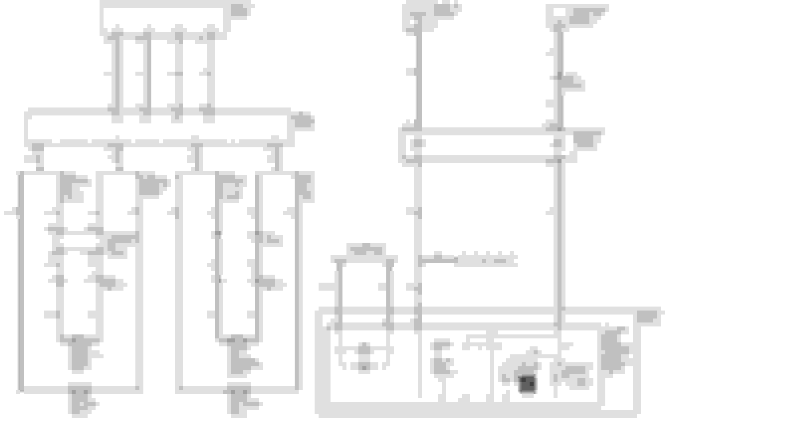
This is the rest of the schematic you're looking for.
I read the same thing about it being able to take all of the different switches on a single input.
In order to get the HFL wires into the JEXR though you'll have to pass a wire from the ceiling down to the radio and then take it off there as I mentioned before either by using one of the OEM wires or running your own wire. So you'll need to use 2x of the JEXR inputs to get all of the buttons, or splice the positive wire from the HFL together with the GRN/RED wire for the media buttons and put them all on a single input. I was mistaken earlier as well, pin A3 on the headunit is GRN/RED not ORN/RED.
Here you can see the media button switches have their own ground, so if you take the BRN wire off of A11 on the headunit you can pass that directly into the JEXR as your ground for the buttons.
Can see the 10k ohm resistor I mentioned, the HFL has one of a different resistance in a similar position. I don't know if that is going to effect training the JEXR. The capacitor should have no effect really for this application.
Thanks that's exactly what I was looking for! Yeah I get what you're saying now about that other resistor, I'm getting my joycon today, gonna try messing around with this sometime this week and see how it does, hopefully soon enough than later. I also see what you're saying about the HFL buttons and needing 2 inputs or splicing them together. I wouldn't imagine there would be a problem with splicing them together with the media buttons since they have different values of resistances. If I was to use the HFL buttons though I would probably just go the route of using the second input on the joycon just for certainty, especially since it has a total of 4 inputs anyway.
Also where would you say would be the best place to tap into the GRN/RED and BRN wire for the media buttons? Really don't want to have to pull out the head unit, was hoping I could find the wires in a more accessible spot on their way to it.
You could try finding them on the other end of the cable reel in the steering column, but they may be fairly difficult to identify there. You could pick up the HFL wire there as well and then just run your wires from the back-side of the cable reel.
I think sometimes people have had the cable reel come apart during disassembly of the column before and don't know how safe or accessible those connections would be. The last thing you'd want is it to pop apart and have to go to a salvage yard to get a new one.
I think the easiest place, that I can think of, to get to them is at the back of the headunit. In the column may be easier, but I don't know how much of the column you'd have to disassemble to be able to access them or trying to fish through your harness at the end of the column for those wires.
I think sometimes people have had the cable reel come apart during disassembly of the column
After you're done shitting your pants, it's not the hardest thing in the world. SOURCE: A guy who did it on accident
Once the cables are reinstalled you rotate fully left to the stop position, then turn right 3 revolutions per the service manual. There are two ribbon cables sandwhiched between two film cables for protection. Wear gloves - the lubricant is quite tacky and slick (silcone based)
So I'm happy to say I've got everything wired up and working how it should. It's not hard at all and you don't lose any button functionality and no modding needed! Just simply tapping into the wires behind the steering wheel (which are so easy to get to). The joycon is connected in parallel and all it does is read the different voltages and assigns buttons to the different levels, similar to testing a circuit with a voltmeter, you're not altering the circuit in any way. I'll be sure to post a write-up and a video once I'm done tweaking everything just right and have the time, should be within a couple days. Also got a little extra to show you guys
So I'm happy to say I've got everything wired up and working how it should. It's not hard at all and you don't lose any button functionality and no modding needed! Just simply tapping into the wires behind the steering wheel (which are so easy to get to). The joycon is connected in parallel and all it does is read the different voltages and assigns buttons to the different levels, similar to testing a circuit with a voltmeter, you're not altering the circuit in any way. I'll be sure to post a write-up and a video once I'm done tweaking everything just right and have the time, should be within a couple days. Also got a little extra to show you guys
That's pretty cool I'm glad it works with it in parallel, now you've got me thinking of how I can setup mine on my 2012 Accord haha..
The only thing that I can think of with it setup that way is that the buttons control both units at the same time, the tablet and the headunit. As an example, say we program the volume buttons on the steering wheel for the volume on the tablet. Now when you press the volume up or down it's a BIG step as opposed to a smaller step, since it changes the volume up on the tablet a step and up on the headunit a step instead of just turning the headunit volume up or just the tablet volume up.
The other thing is the button like the mode button or HFL, if you have an HFL in your car and you press the HFL button to interact with the tablet now the stock HFL prompts you and the tablet performs whatever function it is programmed to do with the JEXR. The mode button would swap radio modes and you'd be off your aux input.
So a little downside to it with it wired in parallel, unless your HFL is out then you get those two buttons. I think the channel buttons should work fine though, when you're on an aux input I don't think they do anything anyhow so it'd be easy to program those to swap tracks without worry.
I just got my Joycon and have started getting familiar with the Explorer application. I managed to find some resources on how to get launching of apps working via keyboard input. Should allow me to get all the buttons mapped the way I want.
I got some time tonight so I decided to start identifying the harness wires I need to tie into. I have identified the wires required to patch the HFL controls down to the Head Unit ORG(Pin2) + BLU(Pin7). I'll being using the female connector off my dead blutooth unit so that I don't need to cut wires. I have also found the opposite end of BLU(Pin7) on the Head Unit connection. I have not tested it but thus far it seems like I am good to go on the HFL wires.
Unfortunately there is a but. In this case I can't seem to find a GRN/RED wire on the Head Unit connection. I have mainly been looking at the big Gray connector. Is that the correct one to be looking at?
I suppose I can always tap in behind the steering wheel but I would rather not have to run wires.
Sorry I haven't given an update, been caught up with school. It would be a lot easier just to tap into the wires behind the steering wheel. I placed my joycon next to the nexus and ran the usb wire from the joycon to my hub in the armrest. It's a fairly short distance from the steering wheel to my joycon so wiring wasn't much of a problem, I also have wires coming off the car's navigation buttons so keeping my joycon in that area made things fairly convenient for me. The pictures below shows the connector your need to tap into. I simply stripped a part of the wire and secured the wires from the joycon around them. As you probably know already:
GREY-Navi buttons
ORANGE - HFL buttons
GREEN/RED-Audio Buttons
BROWN-*negative* goes to black wires on the joycon
It's important to know that due to how the car is wired only one set of buttons can be wired per joycon input, the brown wire can be common among inputs though.
Later this week i'll post a video of everything running and also give some details on how I was able to map the buttons below the navigation screen to work with the joycon/nexus
What values did you use for all the buttons?
Since I can't do the wire work in the car till this weekend I would at least like to get the programming out of the way.
What values did you use for all the buttons?
Since I can't do the wire work in the car till this weekend I would at least like to get the programming out of the way.
that's where things get a little complicated lol. As far as what inputs I have going where on the joycon:
Channel A - Phyical Buttons under nav screen
Channel B - Joystick under navi screen
Channel C - Media buttons on streeing wheel
Channel D - Navi buttons on steering wheel
On joycon channel C and D, there can only be 2 buttons per channel so for channel C I assigned forward and back and on channel D I assigned BACK to be play/pause.
For channel A and B things were a bit more involved since I had to change the keymaps in android to get it to do exactly what I want but it wasn't too bad once I figured things out. I was having problems with autodroid so I actually switched back to USBROM. It will take me awhile to fully explain what I did with these 2 channels.
As far as how I wired the buttons under the navi screen this should give you some idea lol. Since the joycon works by detecting different resistances I figured out which wires do what and then figured out how to wire resistors. The nice thing about this is the resistors fit perfectly in the holes on the connector so I didn't have to actually cut or alter anything so if I want to, I can return the car completely back to stock tomorrow if I want.
This thread is why I love Acurazine. I'm absorbing all of this as we speak and I'm no longer frustrated lol. More information to come in a separate thread about a head unit I'm incorporating...
 12-12-2014, 10:43 PM